


Boise State University
Scholar Works
Computer Science Graduate Projects and Theses Department of Computer Science
9-1-2013
Evaluating the Presence of a Victim Cache on an
Arm Processor
Lakshmi Vidya Peri
Boise State University
EVALUATING THE PRESENCE OF A VICTIM CACHE ON AN ARM PROCESSOR
by
Lakshmi Vidya Peri
A project
submitted in partial fulfillment
of the requirements for the degree of
Master of Science in Computer Science
Boise State University
September 2013
© 2013
Lakshmi Vidya Peri
ALL RIGHTS RESERVED
BOISE STATE UNIVERSITY GRADUATE COLLEGE
DEFENSE COMMITTEE AND FINAL READING APPROVALS
of the project submitted by
Lakshmi Vidya Peri
Project Title: Evaluating the presence of a Victim Cache on an ARM processor
Date of Final Oral Examination: 05 September 2013
The following individuals read and discussed the project submitted by student Lakshmi Vidya Peri, and they evaluated her presentation and response to questions during the final oral examination. They found that the student passed the final oral examination.
Gang-Ryung Uh, Ph.D. Chair, Supervisory Committee
Amit Jain, Ph.D. Member, Supervisory Committee
Jennifer Smith, Ph.D. Member, Supervisory Committee
The final reading approval of the project was granted by Gang-Ryung Uh, Ph.D., Chair of the Supervisory Committee. The project was approved for the Graduate College by John R. Pelton, Ph.D., Dean of the Graduate College.
ACKNOWLEDGEMENTS
I would like to thank Dr. Gang-Ryung Uh for his support, patience, guidance and invaluable knowledge extended to me over the last few years. My project would not have been possible without his unending support and mentoring. The help and support he provided me in this journey have been invaluable to me to attain this goal. I am honored and grateful to my committee members Dr. Amit Jain and Dr. Jennifer Smith who provided time and energy to review this project. I would also like to thank my brother, Dr. Ramesh Peri and my sister-in-law, Satya Vadlamani for standing by me like a rock at all the stages of my graduate education without whose support this wouldn’t be possible. I am lucky to have my best friend, philosopher and guide in my ever motivating parents. I would like to thank my friends Prathyusha Kalapala, Rakesh Lohit, Subramanyam Venkataraman, Ganga Pavalarajah and others who were of immense help. They helped me overcome stress and frustration that I faced when I was hitting roadblocks and kept me focused and motivated towards my goal and last but not the least, I thank the Sadguru and God for the immense grace and blessings he has showered on me all through my life to make this possible.
ABSTRACT
Mobile processor is a CPU designed to save power. It is found in mobile computers and cell phones. A CPU chip, designed for portable computers, is typically housed in a smaller chip package, but more importantly, in order to run cooler, it uses lower voltages than its desktop counterpart and has more “sleep mode” capability. A mobile processor can be throttled down to different power levels and/or sections of the chip can be turned off entirely when not in use. ARM is a 32-bit reduced instruction set computer (RISC) instruction set architecture (ISA). The relative simplicity of ARM processors makes them suitable for low power applications. Hence ARM processors
account for approximately 90% of all mobile 32-bit RISC processors. Today, mobile processors are expected to run complex, algorithm-heavy, memory-intensive applications which were originally designed and coded for general purpose processors. Due to this we see a huge impact of the memory latencies on the execution time of applications. To reduce this impact and serve this kind of applications, the relative complexity of ARM processors has increased in the last decade by the inclusion of traditional methods like multiple issue of instructions, out-of-order instruction execution and large, associative caches.
Victim Caching is another method which can be used to reduce the execution time and is currently not incorporated in the ARM processors. This method was proposed by Norman P. Jouppi in his paper “Improving Direct-Mapped Cache Performance by the Addition of a Small Fully-Associative Cache and Prefetch Buffers”. Victim Cache is defined as an extension to a direct mapped cache that adds a small, secondary, fully associative cache to store cache blocks that have been ejected from the main cache due to a capacity or conflict miss. These ejected blocks are likely to be needed again so storing them in the secondary cache should increase performance and reduce the execution times. Therefore for the Master’s project we re-implemented the SimpleScalar simulator
for an ARM processor by incorporating the impact of Victim Cache. This re implementation of the ARM simulator gave a significant improvement in the performance when various applications of MIBench benchmark suite were run on this simulator. It is observed to have a reduction of 1.93% in the number of clock cycles used and increase in the hit rate of Level 1cache by 2.7% over various Level 1 cache and Victim cache configurations on an average. It is also observed that the benefit of Victim cache increases as the size of Level 1 cache decreases and the performance boost obtained by the processor in presence of a Victim cache is comparable to the performance obtained when a Large, Associative Level 1 cache is used. Hence, incorporation of Victim Cache to an ARM processor is highly advantageous to the current generation of Mobile processors instead of using a Large, Associative Level 1 cache.
TABLE OF CONTENTS
ACKNOWLEDGEMENTS ……………………………………………………………………………………….
ABSTRACT ……………………………………………………………………………………………………………..
LIST OF TABLES …………………………………………………………………………………………………..
LIST OF FIGURES ………………………………………………………………………………………………..
CHAPTER 1. INTRODUCTION ………………………………………………………………………………
CHAPTER 2. CONCEPTS ……………………………………………………………………………………….
2.1. Victim Cache and its Functionality………………………………………………………….
2.2. Features of an ARM Cortex-A Series ………………………………………………………
2.2.1. Dhrystone MIPS ………………………………………………………………………..
2.2.2. NEON Technology …………………………………………………………………….
CHAPTER 3. METHODOLOGY ……………………………………………………………………………
3.1. Simple Scalar Toolset …………………………………………………………………………..
3.2. MIBench Benchmark Suite …………………………………………………………………..
3.3. Implementation …………………………………………………………………………………..
3.3.1. Sim-cache Implementation ………………………………………………………..
3.3.2. Simple Scalar ARM simulator Implementation …………………………….
3.4. Implementation of a Static Simulator to Validate the Results ……………………
CHAPTER 4. RESULTS …………………………………………………………………………………………
4.1. Results Obtained …………………………………………………………………………………
4.2. Validating the Results ………………………………………………………………………….
CHAPTER 5. FUTURE WORK ……………………………………………………………………………..
CHAPTER 6. SUMMARY AND CONCLUSION …………………………………………………….
REFERENCES ……………………………………………………………………………………………………….
LIST OF TABLES
Table 4.1. MIBench benchmarks …………………………………………………………………………..
Table 4.2. Comparison of results between Simple Scalar ARM Simulator and a trace driven Cache Simulator…………………………………………………………………..
LIST OF FIGURES
Figure 2.1. Position of a Victim Cache …………………………………………………………………….
Figure 2.2. ARM Cortex-A8 …………………………………………………………………………………..
Figure 3.1. Modified cache_access function and Implementation of v_cache_access function ………………………………………………………………………………………..
Figure 4.1. Percentage Improvement in Hit rate of 256 Set Data L1 cache …………………
Figure 4.2. Percentage Improvement in Hit rate of 128 Set Data L1 cache …………………
Figure 4.3. Percentage Improvement in Hit rate of 64 Set Data L1 cache …………………..
Figure 4.4. Percentage Improvement in Hit rate of 32 Set Data L1 cache …………………..
Figure 4.5. Average Improvement in Hit rate for various for Data L1 configurations …..
Figure 4.6. Percentage of Victim cache Hit rate for 256 Set Data L1 cache ………………..
Figure 4.7. Percentage of Victim cache Hit rate for 128 Set Data L1 cache ………………..
Figure 4.8. Percentage of Victim cache Hit rate for 64 Set Data L1 cache ………………….
Figure 4.9. Percentage of Victim cache Hit rate for 32 Set Data L1 cache ………………….
Figure 4.10. Average Victim cache Hit rate for various Data L1 configurations ………….
Figure 4.11. Percentage Reduction in Clock cycles used for 256 Set Data L1 cache ……
Figure 4.12. Percentage Reduction in Clock cycles used for 128 Set Data L1 cache ……
Figure 4.13. Percentage Reduction in Clock cycles used for 64 Set Data L1 cache ……..
Figure 4.14. Percentage Reduction in Clock cycles used for 32 Set Data L1 cache ……..
Figure 4.15. Average Percentage reduction in Clock cycles used for various Data L1 Configuartions ……………………………………………………………………………….
Figure 4.16. Comparison of Percentage Reduction in Clock cycles when Large, Associative caches and Victm caches are used …………………………………..
CHAPTER 1. INTRODUCTION
The world is rapidly moving towards using mobile devices extensively to communicate, travel with in-built GPS capabilities, browse the internet using Wi-Fi capabilities, read the books, news, articles, etc., play games, store data, listen to music, take pictures and videos, connect to other Bluetooth devices such as an automobile or a microphone headset or a television, remotely operate other electronic devices, capture data with integrated devices like barcode, RFID and smart card readers for business purposes, digitize notes and update themselves with all other day to day scholarly as well as routine chores. The applications of mobile devices are increasing at an exponential rate demanding mobile processors to be equipped to run complex, algorithm-heavy, memory intensive applications which were originally designed and coded for general-purpose processors. To serve these demands, mobile devices are supposed to have a lasting battery life, should be able to multitask and provide very high performance levels. Mobile devices use mobile processors to serve all this purposes.
Mobile processor is a CPU designed to save power. A CPU chip designed for portable computers. It is typically housed in a smaller chip package, but more importantly, in order to run cooler, it uses lower voltages than its desktop counterpart and has more “sleep mode” capability. A mobile processor can be throttled down to different power levels and/or sections of the chip can be turned off entirely when not in use. In 2011, producers of chips based on ARM architectures reported shipments of 7.9 billion ARM-based processors, representing 95% of smart phones, 90% of hard disk drives, 40% of digital televisions and set-top boxes, 15% of microcontrollers and 20% of mobile computers [1].
The ARM architecture describes a family of RISC (reduced instruction set computer)-based computer processors. The name was originally an acronym for Advanced RISC Machine, and in its early days Acorn RISC Machine. ARM processors require significantly fewer transistors than processors that would typically be found in a traditional computer using a RISC based approach to design processors [1]. This approach provides a lot of advantages. They are lower costs, less heat, and less power usage, traits that are desirable for use in light, portable, battery-powered devices such as smart phones and tablet computers. The reduced complexity and simpler design allows companies to build a low-energy system on a chip for a mobile system incorporating memory, interfaces, etc. The relative simplicity of ARM processors makes them suitable for low power applications. Hence, ARM processors are used extensively in mobile devices, including personal digital assistants (PDAs), tablets, mobile phones, digital media and music players, handheld game consoles, calculators and computer peripherals such as hard drives and routers. Hence ARM processors should provide high performance.
The wide range of performance improvement techniques employed by hardware designers together with the scale and intricacy of modern software systems has made it very challenging and difficult to assess performance of a processor. Traditionally performance of a processor is defined in terms of speed i.e.; if we were running a program on two different processors, a processor which can get the job done first is considered to have a better performance. As an individual processor, we are interested in reducing the response time – the time between the start and completion of a task. This is also referred to as execution time. In order to maximize the performance of a processor, we have to minimize response time or execution time for some task. Thus, performance and execution time of a processor X are related as [2] [3]:
Performance X=1/Execution Time X 1.1.
Program execution time is the total time to complete a task which includes memory accesses, input/output (I/O) activities, operating system overhead – everything. Processor users and designers relate different metrics to determine the effect of a design change on the performance of a processor. In this project we are confining ourselves to the CPU performance, thus the bottom-line performance measure is CPU execution time. CPU execution time is calculated using clock cycles and clock cycle time. A simple formula to calculate CPU execution time is [2] [3]:
CPU execution time for a program
=CPU clock cycles for a program Multiply by clock cycle time 1.2.
Alternatively, since clock rate and clock cycle time are inverses,
CPU execution time for a program
=CPU clock cycles for a program Multiply by clock cycle rate 1.3.
The above formula clearly indicates that the hardware designers can improve performance by either reducing the number of clock cycles required for a program or the length of a clock cycle. In this project, we are going to evaluate the performance of mobile processors and in particular ARM processors. Therefore, we are more interested in reducing the number of clock cycles required for a program by keeping the clock cycle time constant as we are considering only an ARM processor. Researchers worked on reducing the clock cycles required by a program and came up with methods like multiple issue of instructions, out-of-order instruction execution and large, associative caches [3].
These methods have shown great impacts on the performance of a processor and hence processor manufacturers have incorporated these methods in their hardware designs and increased the relative complexity of processors in the last decade. The ARM Cortex-A8 and higher versions of ARM processors have incorporated these methods [4]. Victim Caching is another method which can be used to reduce the execution time and is currently not incorporated in the ARM processors [4]. This method was proposed by Norman P. Jouppi in his paper “Improving Direct-Mapped Cache Performance by the Addition of a Small Fully-Associative Cache and Prefetch Buffers” [5]. Victim Cache is defined as an extension to a direct mapped cache that adds a small, secondary, fully associative cache to store cache blocks that have been ejected from the main cache due to a capacity or conflict miss. These ejected blocks are likely to be needed again so storing them in the secondary cache should increase performance and reduce the execution times. Hence the SimpleScalar ARM processor simulator is enhanced to incorporate the concept of victim cache to analyze the performance and power utilized. This project is driven by the following goals:
1. Do we observe the advantage of a victim cache on an ARM processor?
2. Is the advantage of incorporation of a victim cache comparable to that of a large, associative L1 cache in terms of performance?
The rest of this report is organized as follows. Chapter 2 describes the concept of victim cache and its functionality and features of ARM Cortex-A8. Chapter 3 provides an overview of the SimpleScalar toolset, MIBench benchmark suite and the implemented methodology. Chapter 4 describes the simulator statistics in terms of performance and power utilized with various configurations of the L1 and Victim caches. Chapter 5 discusses future work and Chapter 6 concludes.
CHAPTER 2. CONCEPTS
2.1. Victim Cache and its Functionality
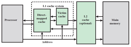
Victim cache was originally proposed by Norman P. Jouppi [5] as an approach to reduce the conflict misses of direct mapped caches without affecting its fast access time. Victim cache is a fully associative cache, whose size is typically 4 to 16 cache lines, residing between a direct mapped L1 cache and the next level of memory. On a main cache miss, before going to the next level, the victim cache is checked. If the address hits in the victim cache the desired data is returned to the CPU and also promoted to the main cache by replacing its conflicting competitor. The data evicted from the main cache is transferred to the victim cache. In case of a miss in victim cache the next level of memory is accessed and arriving data fills the line in main cache while moving the current data to victim cache. In this case the replaced entry in the victim cache is discarded and, if dirty, written back to the next level of memory. The Figure 2.1. shows the position of a victim cache.

The design of a first level cache always involves fundamental tradeoffs between miss rate and access time [6]. Direct mapped caches are simpler, easier to design and require less silicon area than set associative caches. The main disadvantage of a direct mapped cache is the high conflict miss rate where conflict misses typically account for 40% of all direct-mapped cache misses [6]. Conversely for caches with higher associativity the main advantage is lower miss rate, but they are more expensive and incur longer access times. The goal of a computer architect is to maximize performance while staying within cost and power constraints.
Addition of a victim cache can ease this problem by reducing the conflict miss rate to the same extent as a set associative cache, but at the same time maintaining the critical hit access path of a direct mapped cache. Victim cache temporarily holds data evicted from the cache and, because of its fully associative property, it can simultaneously hold many blocks that would conflict in direct mapped cache. If the number of conflicting blocks are small enough to fit in victim cache, both the miss rate to the next memory level and the average access time will be improved due to relatively low miss penalty for fetching from victim cache.
2.2. Features of an ARM Cortex-A Series
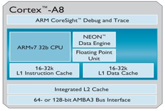
The ARM Cortex-A series [4] applications processors provide an entire range of solutions for devices hosting a rich OS platform and user applications. These devices provide a scalable range of power-efficient performance points for their target applications. Cortex-A8 processor, based on the ARMv7 architecture is a high performance, symmetric, superscalar microarchitecture for dual-issue capability with a high frequency ranging from 600Mhz – 1Ghz through efficient, deep pipeline delivering over 2000DMIPS of performance. It has an advanced branch prediction unit with greater than 95% accuracy and an integrated level 2 cache for optimal performance. It is a proven processor for end devices today due to its NEON technology for multi-media and SIMD processing [4].
2.2.1. Dhrystone MIPS
DMIPS is Dhrystone MIPS. Dhrystone is a synthetic computing benckmark program developed in 1984 by Reinhold P. Weicker intended to be representative of system programming [1]. Dhrystone tries to represent the result more meaningfully than MIPS (million instructions per second) because instruction count comparisons between different instruction sets can confound simple comparisons. For example, the same high level task may require many more instructions on a RISC machine, but might execute faster than a single CISC instruction. Thus, the Dhrystone score counts only the number of program iteration completions per second, allowing individual machines to perform this calculation in a machine-specific way. Common representations of the Dhrystone benchmark are DMIPS obtained when the Dhrystone score is divided by 1757 (the number of Dhrystones per second obtained on the VAX 11/780, nominally a 1 MIPS machine) and DMIPS/MHz, where DMIPS results is further divided by CPU frequency, to allow for easier comparison of CPUs running at different clock rates.
2.2.2. NEON Technology
The ARM Advanced Single Instruction Multiple Data (SIMD) Extension, also known as NEON technology, is a 64/128-bit hybrid SIMD architecture developed by ARM to accelerate the performance of multimedia and signal processing applications [1]. NEON is implemented as part of the processor, but has its own execution pipelines and a register bank that is distinct from the ARM register bank. Key features include aligned and unaligned data access, support for integer, fixed-point and single-precision floating point data types, tight coupling to the ARM core, and a large register file with multiple views. NEON instructions are available in both ARM and Thumb-2. The ARM compiler provides support for Cortex processors equipped with a NEON unit. To generate NEON instructions you must specify a Cortes processor that includes NEON technology on the command line, for example, –cpu=Cortex-A8. There is no NEON support for architectures before ARMv7. Figure 2.2. shows the block diagram of the ARM Cortex-A8 processor.

CHAPTER 3. METHODOLOGY
The following are the tools and methods we used to implement this project:
3.1. Simple Scalar Tool set
To accelerate hardware development, designers often employ software models of the hardware they build. In order to implement this project we need a software model of an ARM processor so as to re-implement the memory hierarchy model to incorporate a victim cache to the processor. Simple Scalar tool set provides an infrastructure for simulation and architectural modeling. It was written in 1992 as part of the Multi scalar project at the University of Wisconsin, under Gurindar Sohi’s direction [7]. The tool set includes sample simulators ranging from a fast functional simulator to a detailed, dynamically scheduled processor model that supports non-blocking caches, speculative execution, and state-of-the-art branch prediction. Hence we used the Simple Scalar tool set to implement this project.
3.2. MIBench Benchmark Suite
To evaluate the performance of an ARM like processor on incorporation of a Victim cache we will need ARM binaries to run on the Simple Scalar ARM simulator. We have to use a standard set of ARM binary applications for this purpose. MI-Bench benchmark suite is a free embedded benchmark suite which is representative of real world applications. Hence we used the MI-Bench benchmark suite to evaluate the presence of a victim cache on an ARM processor using the Simple Scalar simulator.
3.3. Implementation
To enhance the Simple Scalar ARM processor simulator for victim cache, we first installed Simple Scalar ARM simulator (simplesim-arm) and understood its features. This simulator has a 5-stage pipeline with fetch, decode or allocate, execute, write back and commit stages implemented in ruu_fetch(), ruu_dispatch(), ruu_issue(), ruu_writeback() and ruu_commit() functions respectively. The implementation of these stages is discussed below:
1. ruu_fetch(): Fetches the instructions.
2. ruu_dispatch(): Decodes the instructions, allocates them into RUU(Register Update Unit) and LSQ(Load Store Queue) and input/output dependence chains are updated accordingly.
3. ruu_issue(): Issues instructions to functional units to begin execution by checking if there is one available and ensures the instructions memory dependencies are satisfied using the lsq_refresh() function and schedules a writeback event. lsq_refresh() function locates ready instructions whose memory dependencies have been satisfied. This is accomplished by walking through the LSQ.
4. ruu_writeback(): Writes back the completed operation results from the functional units to the RUU at this point and the output dependency chains of completed instructions are checked to determine if any dependent instruction has all of its register operands now. If so the instruction is inserted into the ready instruction queue.
5. ruu_commit(): It commits the results of the oldest completed entries from the RUU and LSQ to the architecture reg file. Stores in the LSQ commit their store data to the data cache at this point as well.
The ARM processor simulator has Register Update Unit(RUU) and Load Store Queue(LSQ) of sizes 8 and 4 respectively with 12 functional units i.e., 4 Integer-ALU’s, 1 Integer-MULT/DIV (IntMULT/IntDIV), 2 Memory Ports (RdPort, WrPort), 4 FP-adder (FloatADD, FloatCMP, FloatCVT) and 1 FP-MULT/DIV (FloatMULT / FloatDIV / FloatSQRT). The branch prediction is implemented in the simulator using 3 types of predictors namely Bimodal predictor, 2-level predictor and combining predictor with a BTB (Branch Target Buffer) each and the simulator’s instruction set is defined in the machine.def file. This ARM simulator implementation includes up to two levels of instruction and data cache (with any levels unified) and one level of instruction and data TLBs using a write back – write allocate cache write policy. We then installed the gcc-arm cross compiler i.e.; arm-linux-gnueabi and its utilities to generate ARM binaries and run on this simulator. We modified a regular expression in the pipe view. pl perl script
from
(/^\*S+(\d+)\S+(\w+)\S+(0x[0-9a-fA-F]+)/)
to
(/^\*S+(\d+)\S+(\w+)\S+(0x[0-9a-fA-F]+)\S+(\d+)\S+(0x[0-9a-fA-F]+)\n?$/)
to view the pipeline stages correctly as this was incorrect and represented the instruction transition to a new stage in the pipeline. We could then visualize the occurrences of cache misses, TLB misses, branch mispredictions, branch misprediction detections and address generation executions in the pipeline view using this perl script correctly and hence obtained a better understanding of the simulator’s working. We then wrote simple 5-10 line ARM assembly instructions to test the concept of Victim cache on this ARM like processor simulator.
3.3.1. Sim-cache Implementation
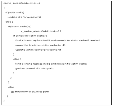
We re-implemented sim-cache.c, a functional cache simulator which generates cache statistics for a user-selected cache and TLB configuration which include up to two levels of instruction and data cache (with any levels unified), and one level of instruction and data TLBs to incorporate victim cache to its memory hierarchy and gauge its effect. To re-implement sim-cache.c with victim cache functionality incorporated, we created another instance of the cache structure with victim cache functionality, modified the L1 cache miss handler function and wrote a victim cache miss handler function in sim cache.c. In order to access the victim cache from a data L1 cache, we modified the cache access function (cache_access()) in cache.c as shown below. The cache_access() function needs a victim cache access function (v_cache_access()) which we implemented in the cache.c file showcasing the functionality of swapping the evicted cache lines back and forth between data L1 cache, victim cache and L2 cache.

3.3.2. Simple Scalar ARM simulator Implementation
The implementation was then extended to re-implement the sim-outorder.c by adding the latencies to access the memory hierarchy so as to calculate the number of clock cycles utilized as sim-outorder.c is a detailed micro-architecture timing model. The memory system is two-level and there is speculative execution support. This is a performance simulator, tracking the latency of all pipeline operations and hence provides us with statistics to evaluate the performance of a processor. The incorporation of victim cache functionality on this ARM like simulator is unique and more effective for the purpose of research in comparison to the other cache memory simulators as it is a complete micro architectural timing model and generates the simulator statistics dynamically unlike other cache simulators which are trace driven and only generate cache statistics [8]. The other advantage of using this ARM like simulator is, it can also be throttled to different levels of processor complexity like choosing the number of instructions being issued, choosing the instruction execution to be in-order or out-of-order, choosing the instruction issue width for the purpose of super scalar implementation, choosing between the different types of branch predictors, etc. In order to test the advantage of Victim cache on an ARM Cortex-A8 like processor we choose the processor to be a dual issue in-order super scalar processor.
3.4. Implementation of a Static Simulator to Validate the Results
In order to validate the results obtained from this dynamic micro-architecture model of the ARM like SimpleScalar simulator, we need to test if the statistics of data L1 cache are generated correctly. Hence we implemented a static simulator to show the functionality of a data level 1 cache. This simulator was implemented in C programming language. It takes a trace of memory references as input and the configuration of the data level 1 cache i.e.; number of sets, line size and associativity as arguments and generates an output determining the number of data level 1 cache assesses, hits and misses. The trace of memory references has the following format:
<accesstype>:<hexaddress>
Where can be characters:
R – Indicates a Read access
W – Indicates a Write access
And is the starting address of the memory reference expressed as a hexadecimal number. This simulator first allocates memory for the data cache using the number of sets and each set is allocated memory based on the associativity of the cache. Then the trace file trace.dat is read by calling the readTrace() function and this stream of references is counted and stored. simulate Data Cache() function simulates the functionality of data L1 cache by separating the set and tag from each memory reference and checks if the block of memory is valid in the set and if the tag matches. If the block is valid and if the tag matches, it is a Hit in the data L1 cache else, it is a Miss. When it’s a Hit, the least recently used variable “lru” is updated and dirty bit of the block is set if the memory reference access type is “W”. When it is a Miss, the valid bit of the block which is obtained after replacing the least recently used block is set, the “lru” variable is updated and the dirty bit is set if the memory reference access type is “W”. The data L1 cache memory statistics are then printed. These results will be compared to the results obtained from the Simple Scalar ARM like simulator.
In order to generate a trace of the format : used by the static simulator, the Simple Scalar ARM like simulator was modified to add an additional line of code. The line of code added is:
if((cp->name[0]==’d’) && (cp->name[1]==’l’) && (cp->name[2]==’1’))
printf(“%c:0x%x\n”, cmd==Read?’R’:’W’, addr);
where cp is the cache structure and cmd is the variable for Read and Write accesses. The results obtained from the static simulator are then compared with the results obtained from the dynamic micro-architecture SimpleScalar ARM like simulator.
CHAPTER 4. RESULTS
4.1. Results Obtained
The results of the re-implemented ARM simulator were obtained on 32bit Ubuntu OS by running the ARM processor simulator with dual issue of instructions and in-order speculative execution support using MIBench benchmark suite.
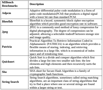
The benchmarks used are tabulated below along with their description:
Table 4.1. MIBench benchmarks

The directly mapped data L1 cache configurations used are:
1. 1KB (32 Lines, 32B/Line)
2. 2KB (64 Lines, 32B/Line)
3. 4KB (128Lines, 32B/Line)
4. 8KB (256Lines, 32B/Line)
The small fully associative victim cache configurations used are:
1. 0.125KB (4Lines, 32B/Line)
2. 0.25KB (8Lines, 32B/Line)
3. 0.5KB (16Lines, 32B/Line)
We plotted the percentage improvement in the total number of clock cycles taken to run the MIBench benchmark suite binaries, percentage improvement in the data L1 cache hit rate and victim cache hit rate. We observed that the number of clock cycles taken to run these binaries is less in number with the presence of a victim cache in the memory hierarchy. This is due to the increase in the number of data L1 cache hits. Figure 4.1. shows the percentage improvement in the hit rate of data L1 cache with 256 sets. This depicts an average of 0.78% improvement in the data L1 cache hit rate over all the benchmarks and configurations. Figure 4.2. shows the percentage improvement in the hit rate of data L1 cache with 128 sets. This depicts an average of 1.98% improvement in the data L1 cache hit rate over all the benchmarks and configurations.
Figure 4.3. shows the percentage improvement in the hit rate of data L1 cache with 64 sets. This depicts an average of 3.19% improvement in the data L1 cache hit rate over all the benchmarks and configurations. Figure 4.4. shows the percentage improvement in the hit rate of data L1 cache with 32 sets. This depicts an average of 4.85% improvement in the data L1 cache hit rate over all the benchmarks and configurations. It is observed that the improvement is the maximum when we have a 0.5KB, 32B/Line fully associative victim cache with all the configurations of directly mapped data L1 cache. Also Figure 4.5.shows that the improvement is the most when a smaller data L1 cache is being used. It is also noticed clearly that there is a great advantage in using a victim cache in the memory hierarchy as the average improvement in the hit rate is about 2.7% over all the configurations. The benchmark jpeg shows the maximum improvement, possibly because it is memory intensive and sha shows the least improvement because it already has a high data L1 hit rate.

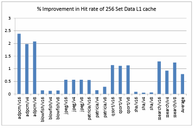


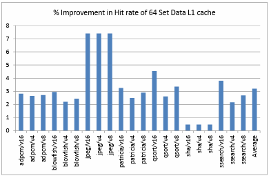
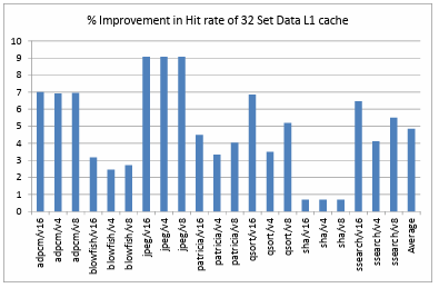

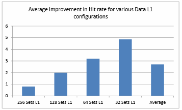
Figure 4.6. shows the comparison of hit rate of victim cache when it is added as an extension to a directly mapped data L1 cache of 256 sets. It depicts that, on an average over all the benchmarks and configurations the victim cache has a hit rate of about 57.48%. Figure 4.7. shows the comparison of hit rate of victim cache when it is added as an extension to a directly mapped data L1 cache of 128 sets. It depicts that, on an average over all the benchmarks and configurations the victim cache has a hit rate of about 54.55%. Figure 4.8. shows the comparison of hit rate of victim cache when it is added as an extension to a directly mapped data L1 cache of 64 sets. It depicts that, on an average over all the benchmarks and configurations the victim cache has a hit rate of about 54.56%. Figure 4.9. shows the comparison of hit rate of victim cache when it is added as an extension to a directly mapped data L1 cache of 32 sets. It depicts that, on an average over all the benchmarks and configurations the victim cache has a hit rate of about 51.76%.
Figure 4.10. shows the comparison of average hit rate for each of the data L1 cache configuration and the average hit rate of all the victim cache and data L1 cache configurations is observed to be 54.59% which is very low compared to data L1 cache average hit rate of 97.89%. It is also observed that as the size of data L1 cache is decreasing the victim cache hit rate is also decreasing. This is an expected behavior from the victim cache as most data locality is already filtered and exploited by the data L1 cache.

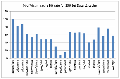

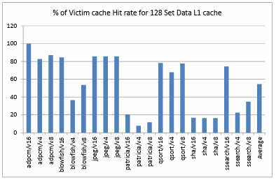
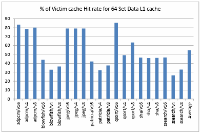

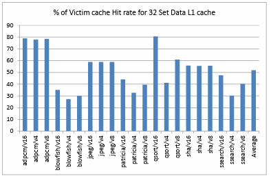

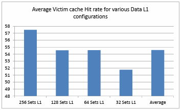
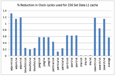
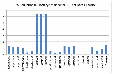
Figure 4.11. shows the comparison of percentage reduction in the clock cycles utilized on a data L1 cache of 256 sets. The performance of the ARM like processor is observed to be enhanced by 0.57% on an average for all the benchmarks and configurations. Figure 4.12. shows the comparison of percentage reduction in the clock cycles
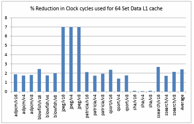
utilized on a data L1 cache of 128 sets. The performance of the ARM like processor is observed to be enhanced by 1.54% on an average for all the benchmarks and configurations. Figure 4.13. shows the comparison of percentage reduction in the clock cycles utilized on a data L1 cache of 64 sets. The performance of the ARM like processor is observed to be enhanced by 2.4% on an average for all the benchmarks and configurations.
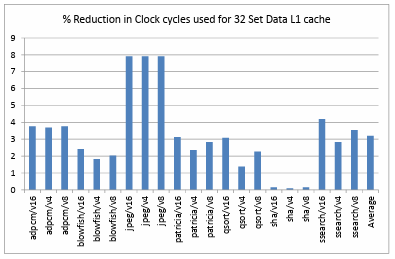
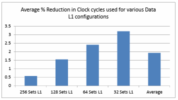
Figure 4.14. shows the comparison of percentage reduction in the clock cycles utilized on a data L1 cache of 32 sets. The performance of the ARM like processor is observed to be enhanced by 3.19% on an average for all the benchmarks and configurations. It is observed that the smallest data L1 cache with a 0.5KB 32B/Line Victim cache has the best performance improvement over all other configurations used. Figure 4.15. shows the comparison of average percentage reduction in the clock cycles utilized on all the data L1 cache and victim cache configurations. It is clearly noticeable that the performance of the ARM like processor is enhanced by 1.93% on average in the presence of a Victim cache over all the Victim cache and data L1 cache configurations. The benchmark jpeg shows the maximum benefit and sha shows the least benefit due to high and low utilization of victim cache respectively.


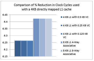
These statistics also clearly depict that the combination of a small directly mapped data L1 cache with a small fully associative victim cache gives the best performance and hit rate results in comparison to the other combinations used. Therefore using a victim cache in combination with a directly mapped L1 cache is advantageous over using only a directly mapped L1 cache. Figure 4.16. shows the comparison of percentage reduction in clock cycles on a 4KB directly mapped data L1 cache when different victim cache configurations and large associative L1 cache configurations are used. Based on the obtained results the advantage of using a small fully associative victim cache with a directly mapped L1 cache is comparable to that of a large associative cache in terms of performance but large, associative caches are expensive, utilize more area and more control units are incorporated in the design. Hence we can infer that the incorporation of a victim cache with a directly mapped cache is advantageous even over an associative cache for an ARM like processor.

4.2. Validating the Results
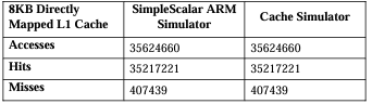
In order to validate the obtained statistics we generated a trace file for the jpeg benchmark using the Simple Scalar ARM simulator for an 8KB directly mapped L1 cache which contains memory references of the following format:
<R/W>:0xaddr
We fed this trace file with the stream of memory references to another cache memory simulator that was implemented. This cache memory simulator simulates the functionality of data L1 cache. It takes the trace file and provides the cache statistics like number of cache accesses, hits, and misses. These statistics were compared with the obtained results from the SimpleScalar ARM simulator. This comparison is tabulated below and we can see that the results match and hence are validated.
Table 4.2. Comparison of results between Simple Scalar ARM Simulator and a trace driven Cache Simulator.

CHAPTER 5. FUTURE WORK
The incorporation of a victim cache can be extended to higher end processors which are designed with high efficiency, superscalar, out-of-order execution support, speculating dynamic length pipeline in-order to evaluate performance as this project was done to evaluate the performance of a highly efficient, dual issue superscalar, in-order, speculative dynamic length pipeline processor which is like ARM Cortex-A8. Victim Cache can also be incorporated in the memory hierarchy design of multi-core processors as the next generation mobile processors highly rely on multi-core processors so as to test the their performance improvement by incorporating it both on local and shared caches and having a proper mechanism to handle the valid blocks in the L1 cache. An additional concept of predicting the reusability of victim blocks will help in the performance improvement of a processor as L1 cache and victim cache do not distinguish between victims that are likely to be used again and those that are not. If a prediction mechanism determines the reusability of an evicted L1 cache block it will be placed in the victim cache else it can be written back into the second level of the memory hierarchy.
This concept will enable obtaining a larger number of L1 cache hits by predicting if a cache block will be reused. Hence this could be a concept for speculation in the future to improve performance of processors.
CHAPTER 6. SUMMARY AND CONCLUSION
This project incorporated a victim cache functionality on an ARM like processor simulator to evaluate its performance. This was done in-order to improve the performance of current generation mobile processors as 90% of mobile processors used are ARM processors [1]. The simplescalar ARM simulator was re-implemented with the incorporation of the concept of victim cache for this purpose. Various ARM binaries from the MIBench benchmark suite were run on this simulator to obtain the performance statistics. These results were then verified using another static cache memory simulator. The scope of work in this project included analysis and experiments to analyze the following questions.
1. Do we observe the advantage of a victim cache on an ARM processor?
2. Is the advantage of incorporation of a victim cache comparable to that of a large, associative L1 cache?
The answers to the above questions can be found in the discussion that follows. We observed that the performance of an ARM like processor is improved by 1.93% when a victim cache is used as an extension to a directly mapped L1 cache and the statistics obtained with the incorporation of a victim cache are comparable to statistics obtained when the L1 cache is large and associative. Therefore using a victim cache is more beneficial over using associative caches as they are more expensive. This benefit varies for different applications. These results were obtained by taking an average of all the results of the MIBench benchmark suite. Based on the obtained results it was established that a smaller directly mapped L1 cache with a small fully associative victim cache gives the best performance results by improving the L1 cache hit rate. Hence an ARM processor with a victim cache will be advantageous to the mobile devices as it depicts a significant improvement in the performance enabling them to be more efficient.
REFERENCES
1. “ARM Architecture,” [Online]. Available:
http://en.wikipedia.org/wiki/ARM_Architecture. [Accessed 16 August 2013].
2. David A. Patterson, John L. Hennessy, Computer Organization and Design, The Hardware-Software Interface., 4th ed., 2011.
3. John L. Hennessy, David A. Patterson, Computer Architecture, A Quantitative Approach., 4th ed., 2007.
4. “Cortex-a,” [Online]. Available: http://www.arm.com/products/processors/cortex-a/index.php. [Accessed 16 August 2013].
5. Norman P Jouppi, “Improving Direct-Mapped Cache Performance by Addition of a Small Fully-Associative Cache and Prefetch Buffers,” in Proceedings, The 17th Annual International Symposium on Computer Architecture., March 1990.
6. “CPU Cache,” [Online]. Available: http://en.wikipedia.org/wiki/CPU_cache. [Accessed 16 August 2013].
7. “SimpleScalar Toolset,” [Online]. Available: www.simplescalar.com. [Accessed 10 September 2011]. 36
8. “Victim Cache Simulator,” [Online]. Available: http://www.ecs.umass.edu/ece/koren/architecture/VCache/home.htm.
9. Paul Genua, “A Cache Primer,” in Freescale Semiconductor AN2663 Rev. 1., Austin TX, 2004.
10. Umang Choudhary, Pratik Phadke, Vasundhara Puttagunta, Supreeth Udayashankar, “Analysis of Sub-block Placement and Victim Caching Techniques.,” [Online]. Available: http://citeseerx.ist.psu.edu/viewdoc/summary?doi=10.1.1.88.9684. [Accessed 19 August 2013].
11. Afrin Naz, Mehran Rezaei, Krishna Kavi and Philip Sweany, “Improving Data Cache Performance with Integrated Use of Split Caches, Victim Cache and Stream Buffers.,” in Proceedings of the 2004 workshop on MEmory performance: DEaling with Application, systems and architecture, 2004.
12. James E. Bennett, Michael J. Flynn, “Reducing Cache Miss Rates Using Prediction Caches.,” 1996. [Online]. Available: http://citeseerx.ist.psu.edu/viewdoc/summary?doi=10.1.1.39.9004. [Accessed 17 August 2013].
13. Gokhan Memik, Glenn Reinman, William H. Mangione-Smith, “Reducing enery and delay using efficient victim caches.,” in Proceedings of the 2003 international symposium on Low power electrinics and design, 2003.
14. Dimitrios Stiliadis, Anujan Varma, “Selective Victim Caching: A Method to Improve the Performance of Direct-Mapped Caches,” IEEE Transactions on Computers, 1997.
15. Walter W. Schilling jr, Mansoor Alam, “The Impact of Prefetching and Victim Caching on Computer Systems Performance,” [Online]. Available: http://citeseer.uark.edu:8080/citeseerx/viewdoc/summary;jsessionid=4801C E22DAC7C30FE1C69096B09A4D33?doi=10.1.1.40.5887. [Accessed 18 August 2013].
16. Samira M. Kham, Daniel A. Jimenez, Doug Burger, Babak Falsafi, “Using dead blocks as a virtual victim cache.,” in Proceedings of the 19th international conference on Parallel architectures and compilation techniques., 2010.